Domain Partitioning
When a large-scale mesh is analyzed in parallel using multiple processes, the single-domain mesh must first be divided into subdomains and the information required for assigning each process and for inter-domain communication must be generated in advance. This preprocessing step is called domain partitioning.
In FrontISTR parallel computation, hecmw_part1 partitions a single-domain mesh into subdomains and creates distributed mesh data. The generated distributed mesh data is read by parallel fistr1 and used by the parallel solver together with the information required for inter-domain communication.
This page describes the partition type, partitioning method, overlap depth, and handling of contact points selected for domain partitioning. For the hecmw_part1 execution procedure, specific control-file syntax, and error messages, see the related topics.
Overview
Domain partitioning is the process of dividing a single-domain mesh into multiple subdomains. FrontISTR creates distributed mesh data by combining a partition type, partitioning method, number of domains, and overlap depth.
| Selection axis | Main options | Role |
|---|---|---|
| Partition type | Node-based partitioning, element-based partitioning | Determines whether ownership is assigned by node or by element. |
| Partitioning method | RCB, METIS (pMETIS / kMETIS) | Determines how domain boundaries are created. |
| Number of domains | Any positive integer (\(2^n\) for RCB) | Determines the number of subdomains in the distributed mesh data. Normally this is matched to the number of MPI processes. |
| Overlap depth | Integer of 1 or greater | Determines the range redundantly retained by neighboring domains. Specified for node-based partitioning. |
| Communication tables | Import/export information, shared information | Defines the data exchange required between neighboring subdomains. Generated automatically during domain partitioning. |
Because the communication tables are included in the distributed mesh data, users normally do not need to edit them directly. Parallel fistr1 reads the distributed mesh data and solves the linear equations using a parallel direct method such as MUMPS or an iterative method.
Choosing a Domain Partitioning Configuration
For ordinary structural and heat-conduction analyses, node-based partitioning should generally be considered first. Node-based partitioning makes communication of nodal values required in parallel finite element analysis straightforward and also allows the overlap depth to be specified. Element-based partitioning is an option for applications such as coupled analysis where the partitioned information is to be handled primarily by element.
Choose the partitioning method based on the geometry and the number of domains. For simple geometries where the number of domains can be \(2^n\), RCB is a simple and stable choice. For complex geometries or when an arbitrary number of domains is required, METIS, which is based on graph partitioning, is a candidate.
| Problem characteristics | Recommended choice |
|---|---|
| Standard parallel structural or heat-conduction analysis | Node-based partitioning |
| Applications using element-centered distributed information, such as coupled analysis | Element-based partitioning |
| Simple geometry close to a rectangular solid, with \(2^n\) domains | RCB |
| Complex geometry or arbitrary number of domains | METIS |
| Contact or MPC-constrained problems using the SAINV preconditioner | Use node-based partitioning with an overlap depth of 2 or greater |
The number of domains is normally matched to the number of MPI processes. For the parallel execution procedure and specification of the process count, see Parallel Analysis. For the relationship between the SAINV preconditioner and overlap depth, also see Solver and Preconditioners.
Partition Types
The partition type determines which mesh entity is assigned unique ownership by a subdomain. Node-based partitioning assigns ownership to nodes, whereas element-based partitioning assigns ownership to elements. In both cases, information required for computation with neighboring subdomains is retained as overlap data.
Node-Based Partitioning
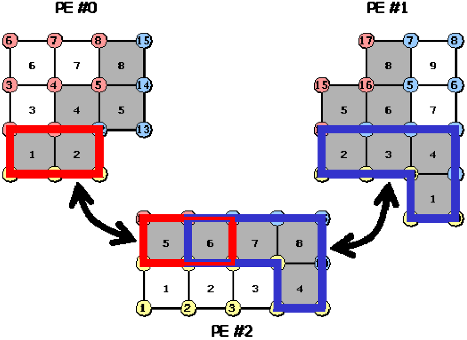
In node-based partitioning, each node is assigned to exactly one owning subdomain. Elements are retained with overlap in neighboring subdomains. In the input, this is specified with !PARTITION, TYPE=NODE-BASED.
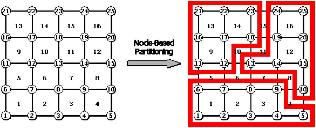
Each subdomain retains its internal nodes, the elements containing those internal nodes, and the nodes constituting those elements.
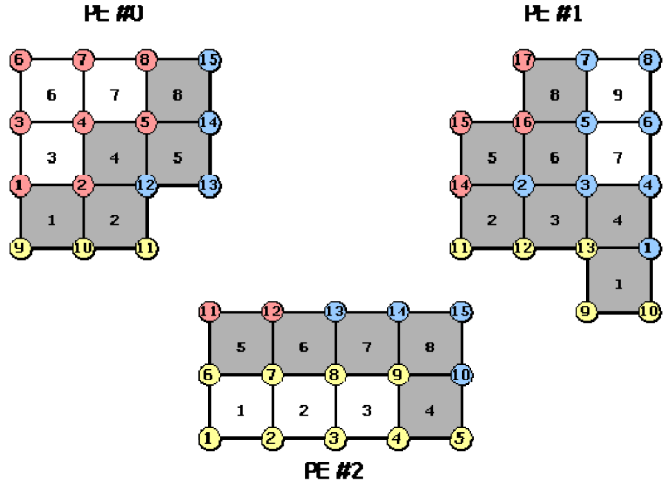
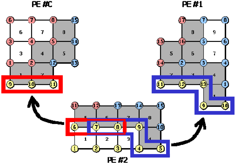
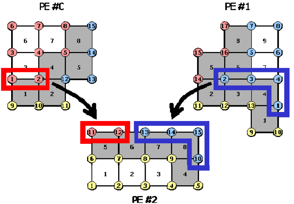
The communication tables for node-based partitioning contain the following information.
- Import nodes: Nodes used in a subdomain that are owned by another subdomain.
- Export nodes: Internal nodes that are import nodes of another subdomain.
- Shared elements: Elements shared with other subdomains.
Element-Based Partitioning
In element-based partitioning, each element is assigned to exactly one owning subdomain. Nodes are retained with overlap in neighboring subdomains. In the input, this is specified with !PARTITION, TYPE=ELEMENT-BASED.
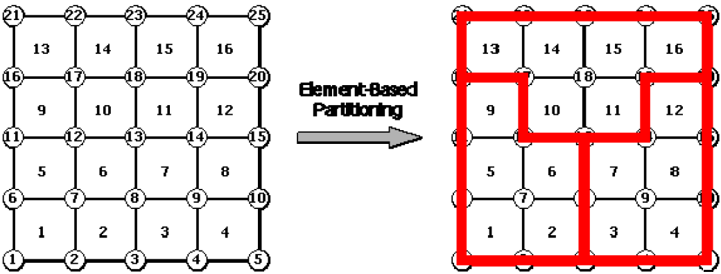
Each subdomain retains its internal elements, the nodes constituting those internal elements, and the elements containing those nodes.
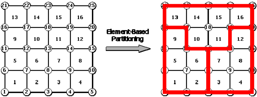
The communication tables for element-based partitioning contain the following information.
- Import elements: Elements used in a subdomain that are owned by another subdomain.
- Export elements: Internal elements that are import elements of another subdomain.
- Shared nodes: Nodes shared with other subdomains.
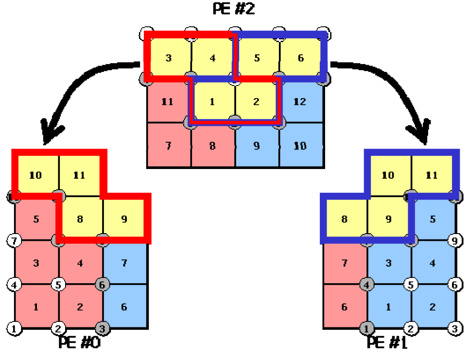
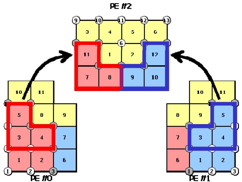
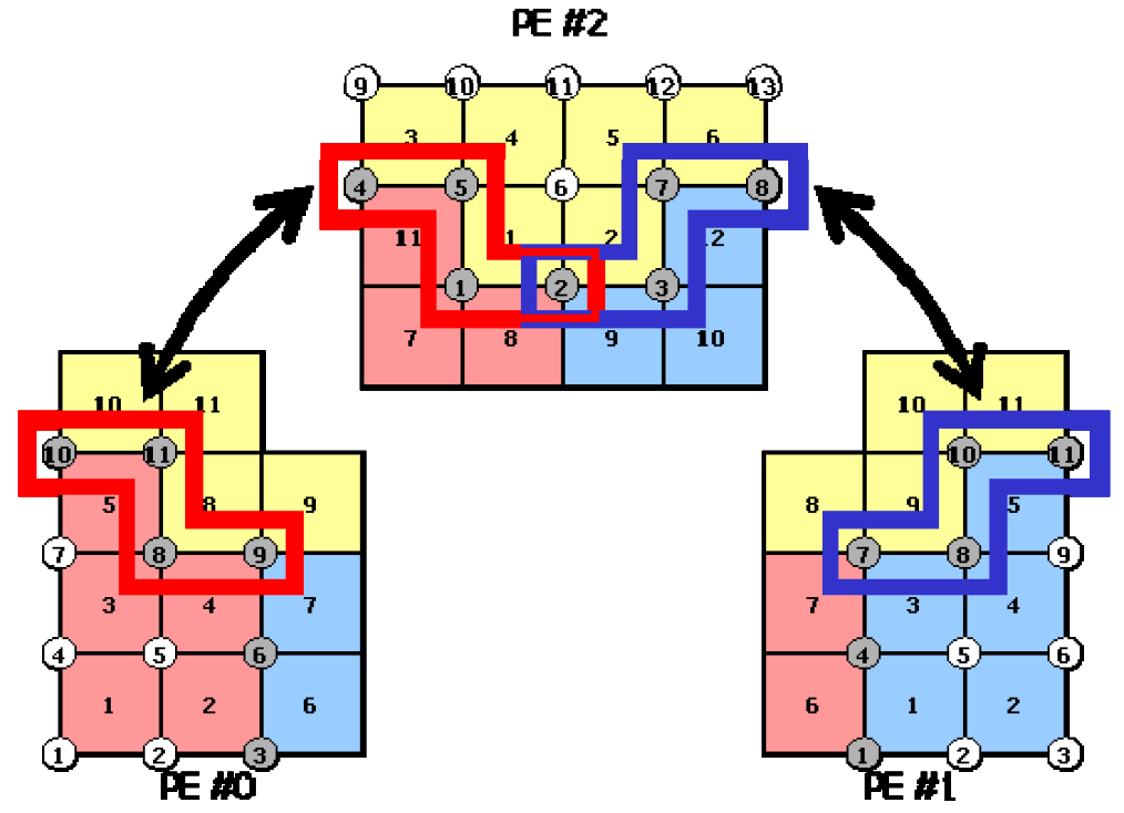
For either partition type, hecmw_part1 automatically generates the communication tables and writes them to the distributed mesh data. Therefore, users do not normally need to create import/export information directly.
Partitioning Methods
The partitioning method determines how subdomain boundaries are created. FrontISTR supports coordinate-based RCB and graph-partitioning-based METIS.
| Partitioning method | Characteristics | Main constraints and notes |
|---|---|---|
| RCB | Recursively bisects the mesh based on coordinate values. Provides fast partitioning for simple geometries. | The number of domains is limited to \(2^n\). Partitioning axes must be specified. |
| pMETIS | Uses graph partitioning while considering connectivity between domains. | Available in builds with METIS enabled. |
| kMETIS | Uses multiway graph partitioning, making it suitable for creating domain boundaries in complex geometries. | Available in builds with METIS enabled. |
RCB stands for Recursive Coordinate Bisection and repeatedly bisects the mesh along coordinate axes. It is suitable when the number of domains can be \(2^n\) and is easy to use for simple, box-like geometries.
METIS treats mesh connectivity as a graph and creates subdomains by graph partitioning. It is a candidate for complex geometries or when the number of domains should not be restricted to \(2^n\). To use METIS, the METIS library must be enabled at build time. For dependency handling, see Required and Optional Dependencies.
Overlap Depth
The overlap depth is the number of layers in the range redundantly retained by neighboring subdomains. For node-based partitioning, !PARTITION allows an integer of 1 or greater to be specified with the DEPTH parameter. The default overlap depth is 1.
For ordinary parallel analysis, DEPTH=1 is sufficient. However, when an SAI-family preconditioner such as SAINV is used for a contact problem or a problem with MPC constraints, increasing the overlap depth to 2 or greater may improve preconditioner quality.
An overlap depth of 2 or greater is also required when the selective edge/nodal smoothing formulation (FORM341=SELECTIVE_ESNS) is used with first-order tetrahedral element 341 in MPI parallel computation. Edge-based and node-based smoothing average quantities over elements adjacent to the target element, so assembling stiffness within a subdomain requires information from elements two adjacency layers away; with the default DEPTH=1, smoothing near domain boundaries is insufficient. For details of the element formulation, see Element Library.
Increasing the overlap depth increases the number of nodes and elements retained by neighboring subdomains, thereby increasing both memory usage and communication volume. Set it by balancing improved convergence against increased computational cost. For preconditioner selection, see Solver and Preconditioners.
Handling Contact Points
When partitioning a mesh containing contact pairs, !PARTITION allows the CONTACT parameter to be used to specify the domain-placement policy for contact points. Contact-point placement affects the stability and communication volume of parallel analyses involving contact search and contact constraints.
| Value | Role |
|---|---|
DEFAULT |
Uses the standard placement policy. |
SIMPLE |
Uses placement close to ordinary partitioning without assigning special weights to contact points. |
AGGREGATE |
Partitions in a manner that tends to group nodes associated with contact pairs. |
DISTRIBUTE |
Partitions so that master-side contact nodes are less likely to be concentrated in particular subdomains. |
For meshes without contact, the CONTACT parameter generally requires no attention. If convergence or load balancing is problematic in parallel analysis involving contact, review the contact-point placement policy. For details of the input syntax, see !PARTITION.
Outputting a Domain Partitioning Image
With !PARTITION, specifying the UCD parameter outputs a UCD file for checking the partitioning result. The UCD file can be used with visualization tools such as MicroAVS to inspect domain numbers and partition boundaries.
After changing the number of domains, partitioning method, or overlap depth, it is important to check for imbalance among the partitioned domains or unnatural fragmentation. UCD output is an auxiliary function for verifying the validity of the partitioning before running the parallel analysis.
Related Topics
- Parallel Analysis —
hecmw_part1execution procedure, input files, and verification of distributed mesh data output. - Solver and Preconditioners — Parallel solvers, preconditioners, and the relationship between SAINV and overlap depth.
- Error Message List — Representative error messages from
hecmw_part1andfistr1. - Parallel Finite Element Method — Theoretical background of domain decomposition and parallel finite element methods.
- !PARTITION — Input syntax for the domain partitioning utility control data.